AWS VPC Deep Dive: Three Hands-On Networking Builds
I built these three networks to understand AWS networking as one full traffic path. I didn’t want to just learn a pile of separate resources. I started with public and private subnets. Then I added controlled outbound access and a bastion. Next I connected two VPCs with peering. Last, I built a segmented hub-and-spoke design with AWS Transit Gateway.
I kept asking one question the whole time. For any packet, what route does it take, and what could allow or block it?
NAT gateways, Transit Gateway attachments, Elastic IPs, and running EC2 instances all cost money. I deleted everything after testing.
Part 1: Public and private subnets
Goal
I put a bastion host in a public subnet and an app server in a private subnet. The app server had no public IP. It could still start outbound traffic through a NAT gateway.
Internet
   |
Internet Gateway
   |
Public subnet: Bastion + NAT Gateway
   |
Private subnet: Application server
1. Creating the VPC and subnets
I created Lab VPC with the CIDR block 10.0.0.0/16.
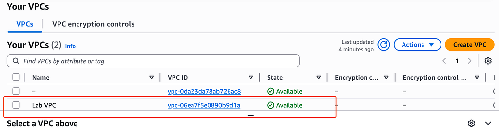
The new Lab VPC in the VPC console
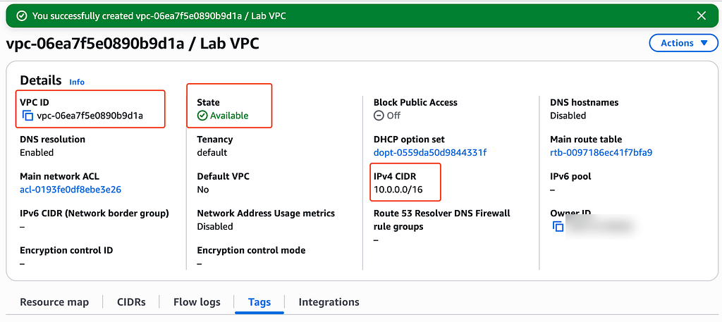
Lab VPC available with the 10.0.0.0/16 IPv4 CIDR
Inside it I created:
- Public subnet:
10.0.0.0/24 - Private subnet:
10.0.2.0/23
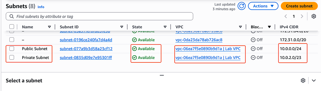
The public and private subnets inside Lab VPC
I kept both subnets in one Availability Zone to stay small. A resilient production layout repeats the public and private tiers across several zones.
2. Attaching an internet gateway
I created an internet gateway and attached it to the VPC.
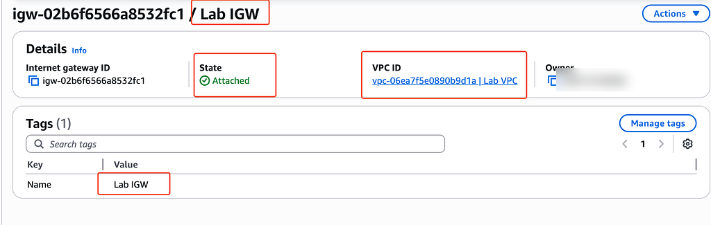
The Lab internet gateway attached to Lab VPC
Attaching an internet gateway doesn’t make every subnet public. The subnet’s route table and the instance’s public address still decide whether internet traffic has a path.
3. Splitting the route tables
At first the private route table only had the automatic local route for 10.0.0.0/16.
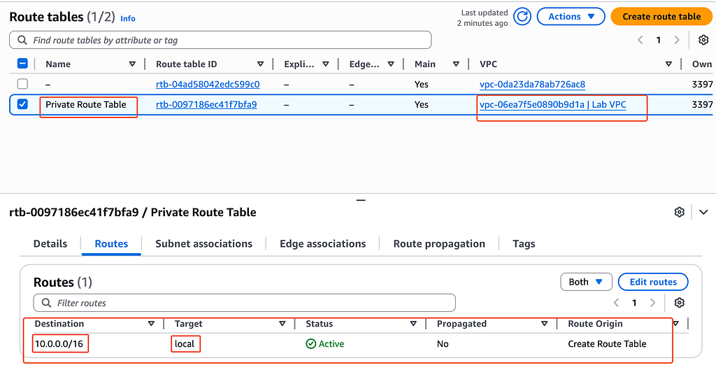
The private route table before NAT was added
I created a separate public route table and associated it with the public subnet. Then I sent 0.0.0.0/0 to the internet gateway.
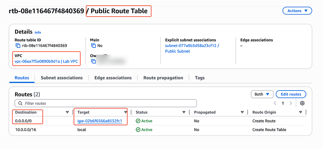
The public subnet’s default route points to the internet gateway
That route is what makes a subnet public. An instance also needs a public IPv4 address or Elastic IP, plus security rules that allow the traffic.
4. Adding NAT for the private subnet
I allocated an Elastic IP address for the NAT gateway.
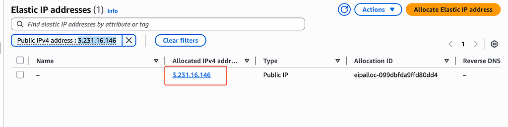
Elastic IP allocated for the NAT gateway
I created a public NAT gateway in the public subnet and waited for it to come up.
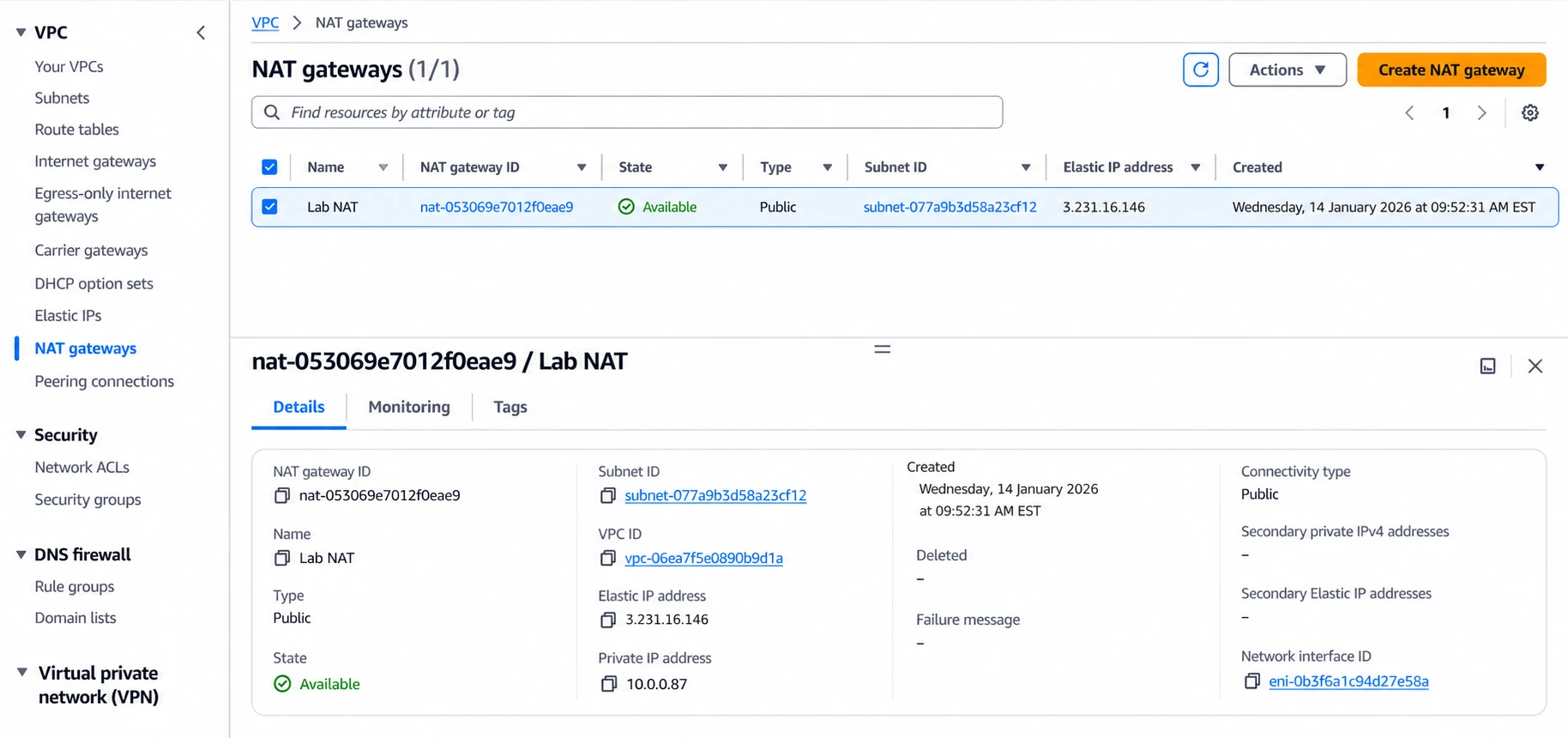
The NAT gateway available in the public subnet
Then I added 0.0.0.0/0 to the private route table with the NAT gateway as its target.
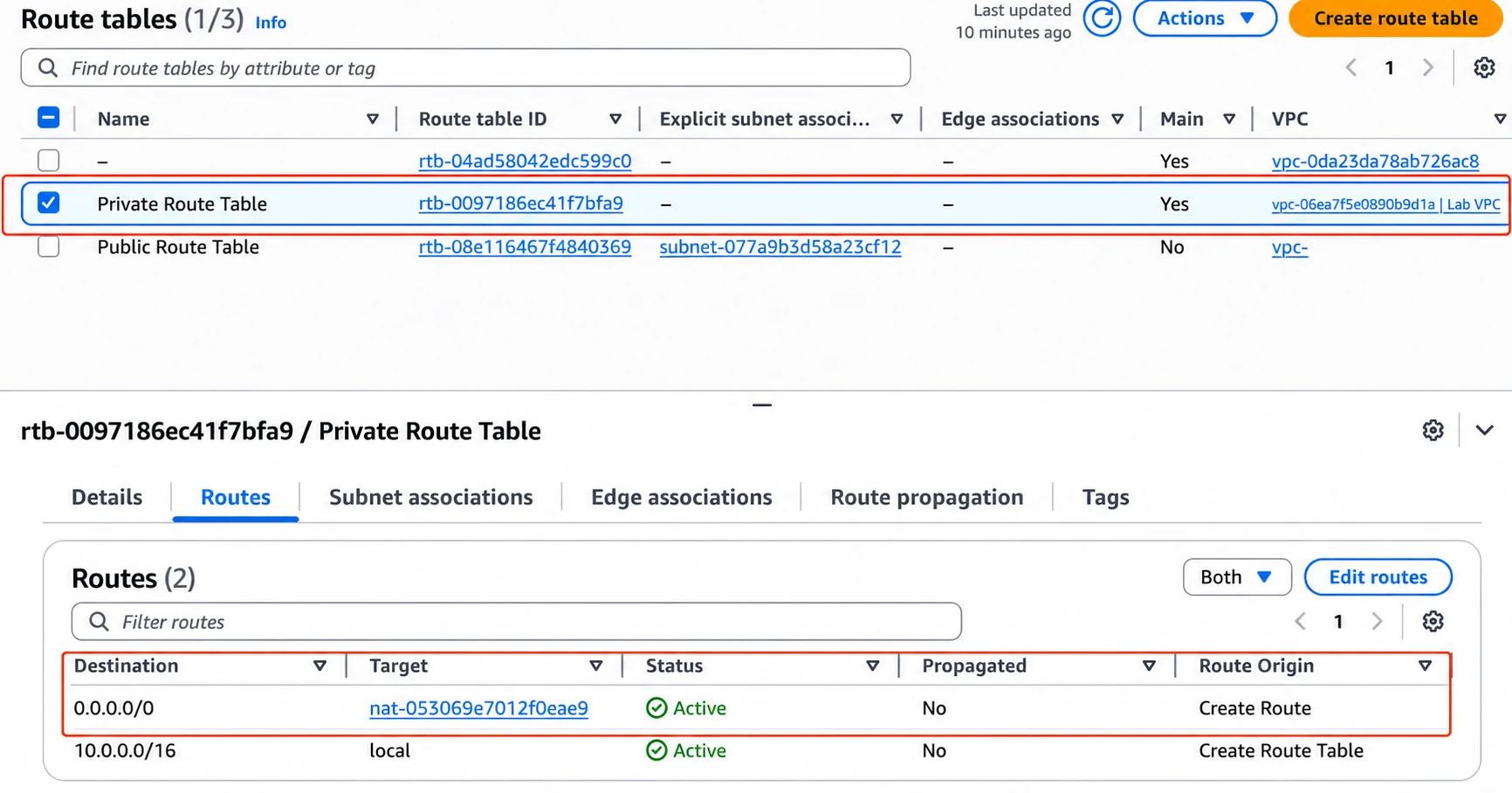
The private subnet’s default route points to the NAT gateway
Now private instances could reach out to the internet over IPv4. Nothing from the internet could reach in uninvited. In production I’d put one NAT gateway in each active zone. Each private subnet would route to the NAT in its own zone.
5. Launching the bastion and private server
I launched an Amazon Linux instance in each subnet. The bastion had a public and a private address.
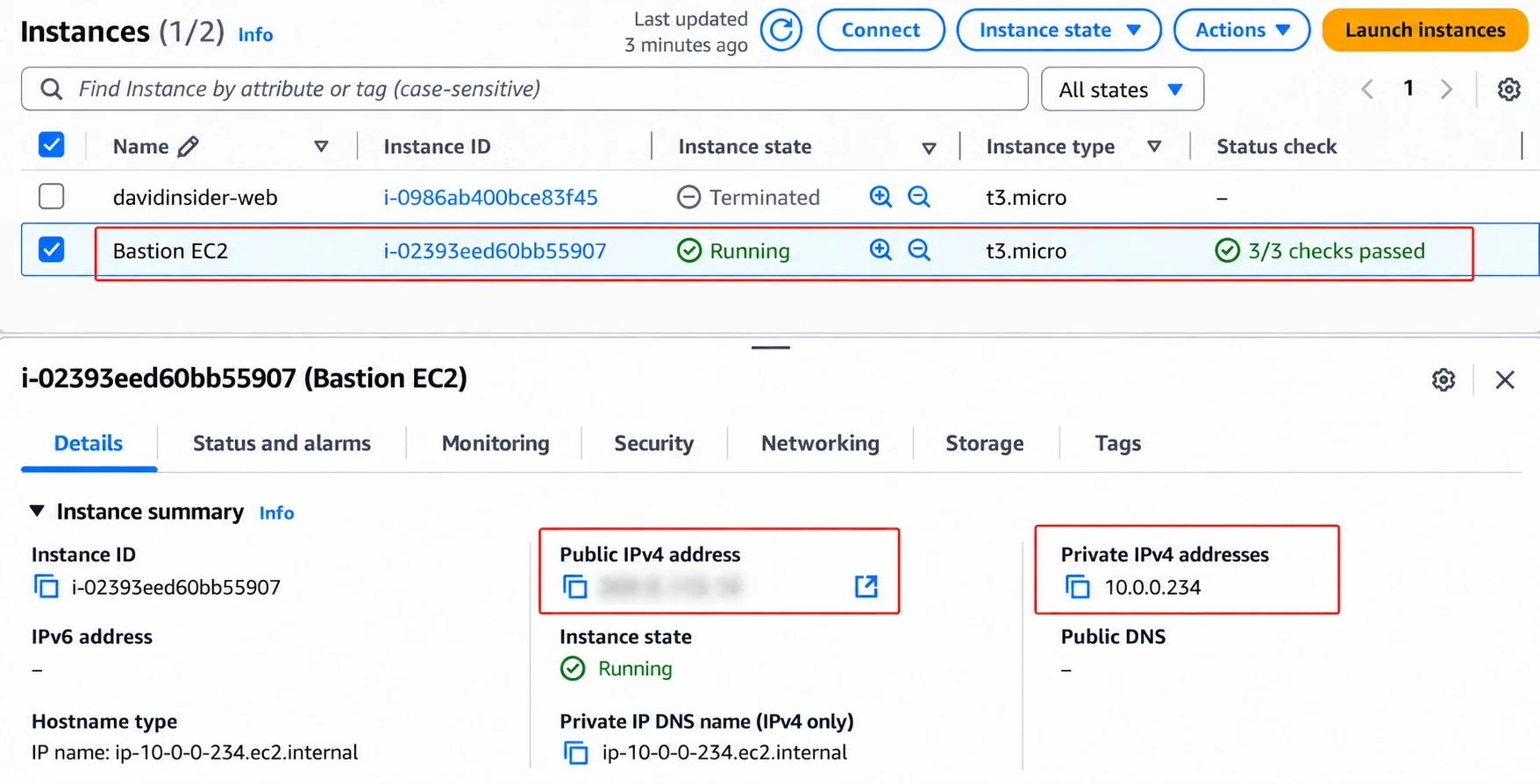
The running bastion instance with public and private IPv4 addresses
The app server only had a private one.
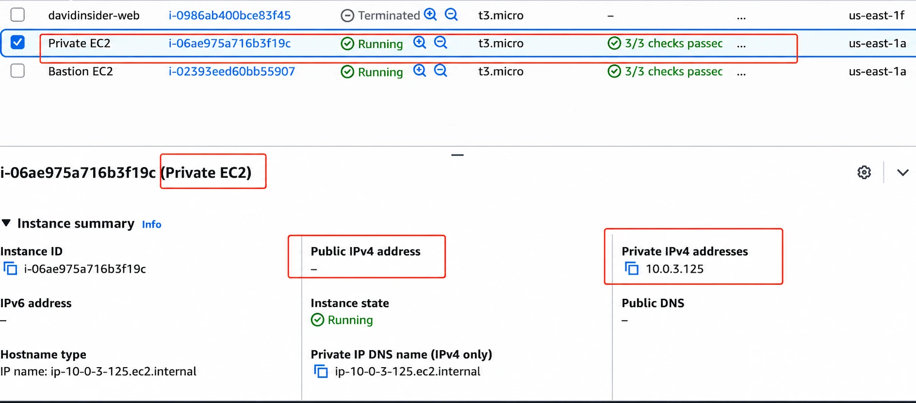
The private application instance has no public IPv4 address
I limited SSH on the bastion to my own public IP with a /32 rule.
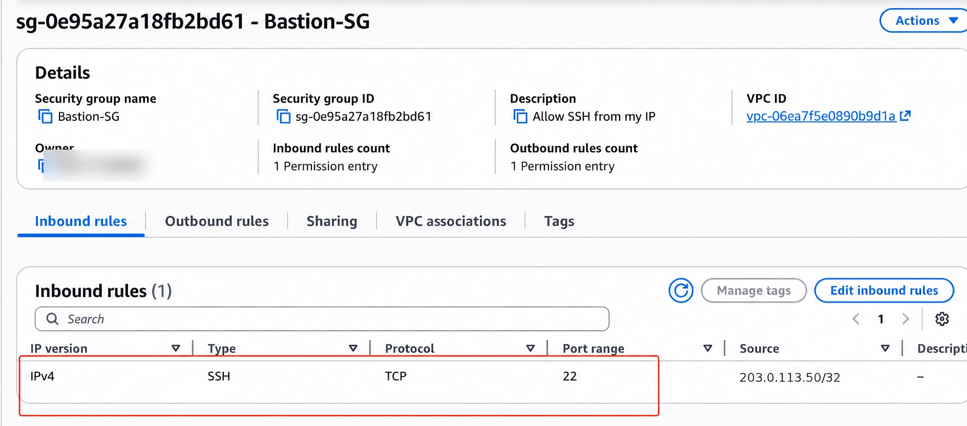
Bastion SSH restricted to one administrator IP
The private server accepted SSH only from the bastion security group.
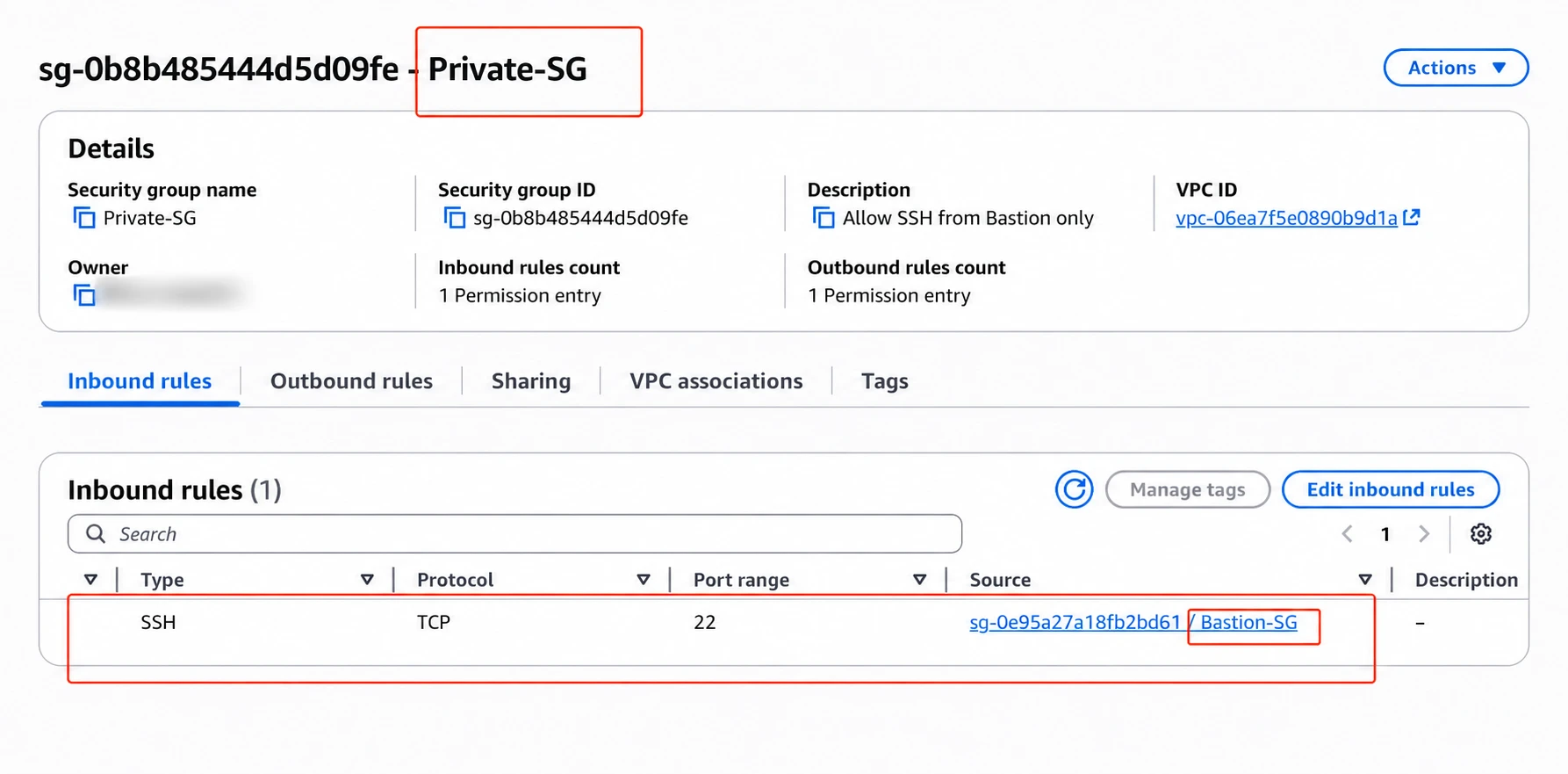
Private-server SSH allowed from the bastion security group
Pointing at the security group was cleaner than hardcoding a private IP. For production I’d rather use Systems Manager Session Manager or another identity-aware method than keep a public bastion.
6. Testing the path
I connected from my laptop to the bastion’s public address.
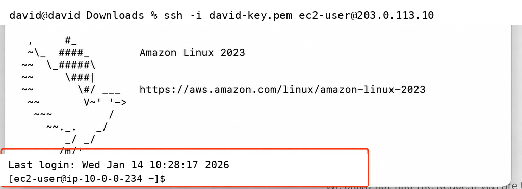
Successful SSH connection to the public bastion
From there I connected to the app server’s private IP. The screenshot shows an SSM-created account. Use whatever username and login method your instance is set up for.
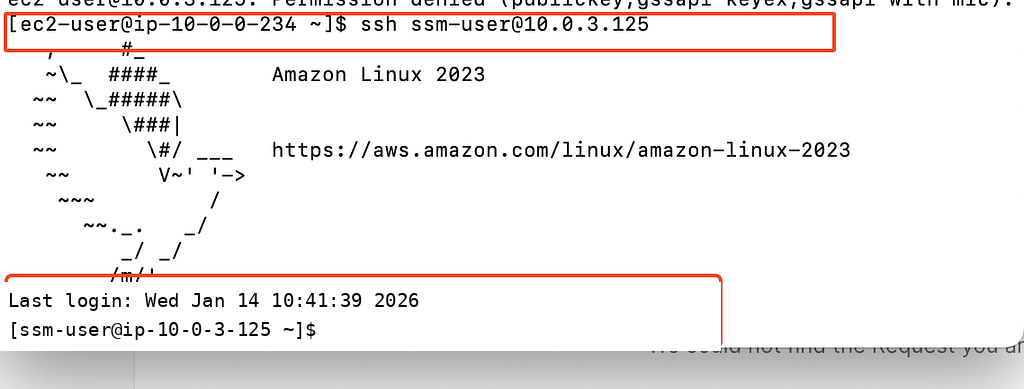
Successful connection from the bastion to the private instance
From the private instance I tested outbound access through NAT.
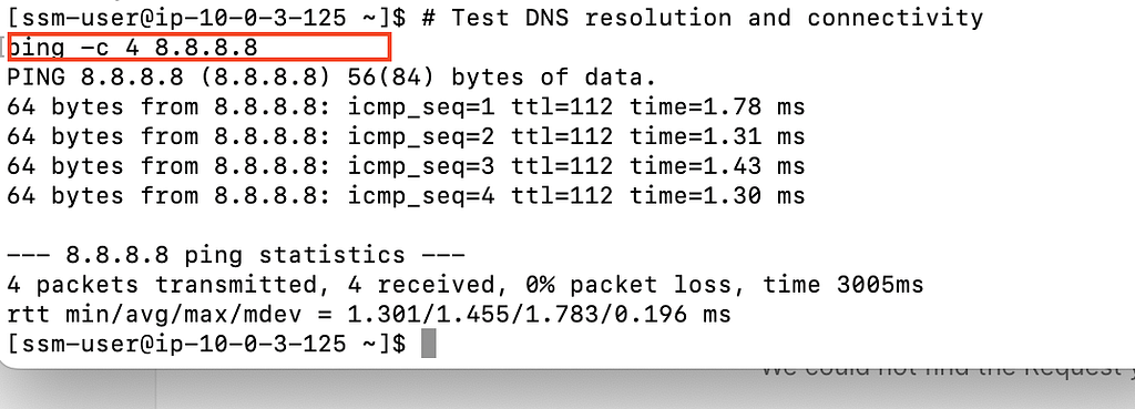
The private instance reaches an external address through NAT
Last, I tried to connect straight from my laptop to the private IP. It timed out like it should. Private addresses aren’t routed over the internet, and the security group only trusted the bastion.
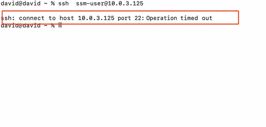
A direct internet SSH attempt to the private address fails
Part 2: Connecting two VPCs with peering
Goal
Next I connected two isolated VPCs over AWS’s private network. I used CIDR blocks that don’t overlap. VPC peering can’t route overlapping ranges.
1. Creating the networks and instances
I created:
- VPC X:
10.1.0.0/16 - VPC Y:
10.2.0.0/16
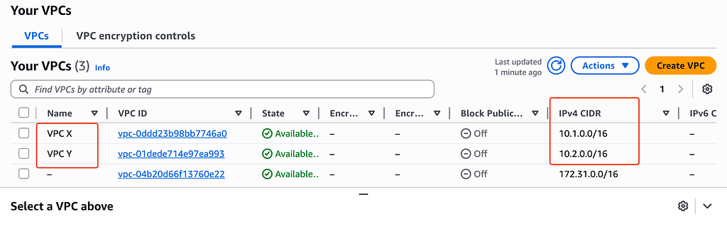
VPC X and VPC Y with non-overlapping CIDR blocks
Each VPC got one test subnet.
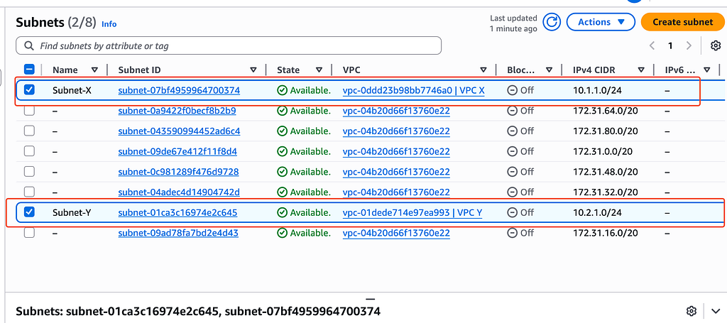
Subnet X and Subnet Y in their respective VPCs
I launched one test EC2 instance in each network.
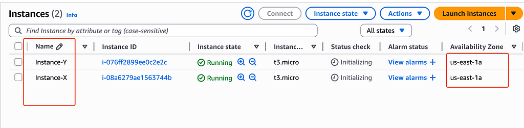
Test instances running in VPC X and VPC Y
2. Setting up security groups
Instance X allowed ICMP and my TCP test port 8000 from VPC Y’s 10.2.0.0/16 range.
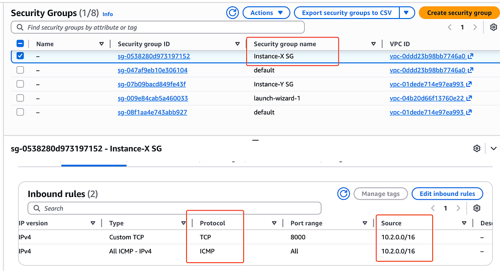
Instance X permits the test traffic from VPC Y
Instance Y had matching rules for traffic from 10.1.0.0/16.
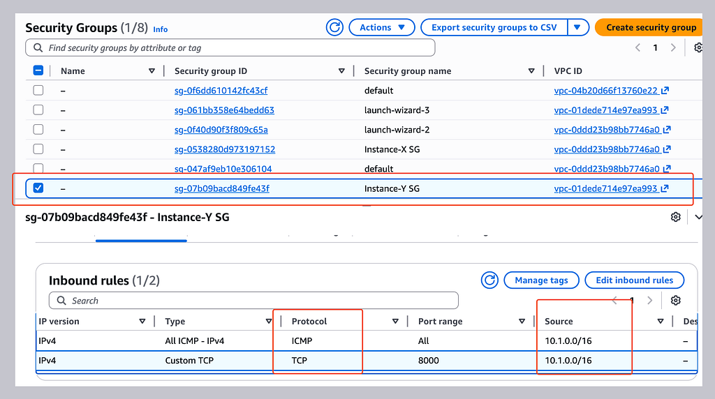
Instance Y permits the test traffic from VPC X
For a real app I’d only allow the exact ports and sources needed. Broad CIDR rules are fine for learning. Security group references or tighter ranges are usually safer.
3. Creating and accepting the peering connection
I requested a peering connection from VPC X to VPC Y and accepted it on the other side.
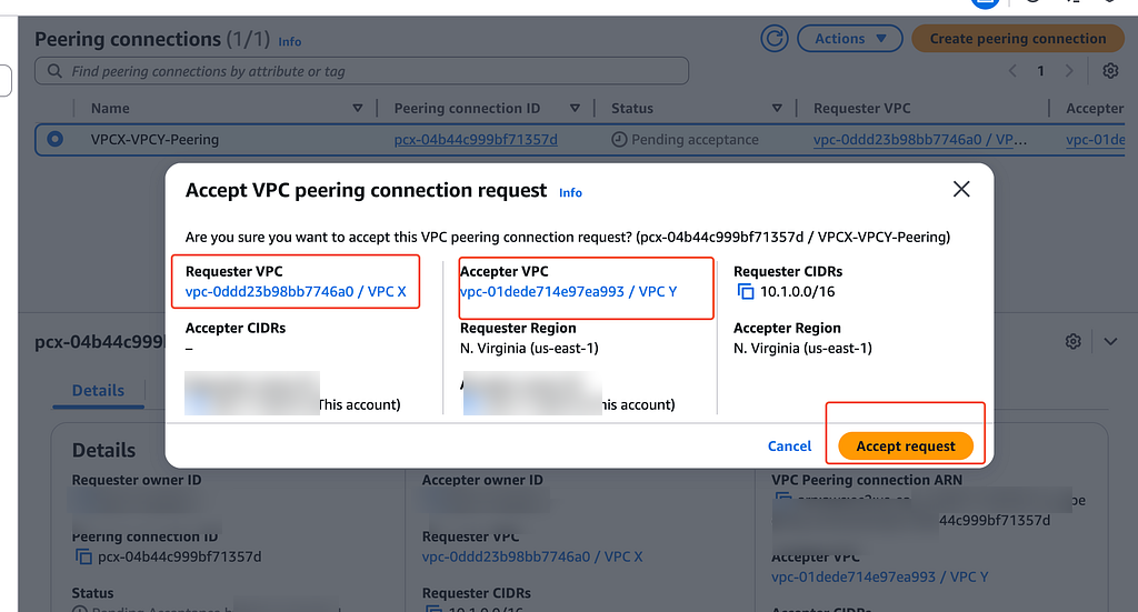
Accepting the peering request between VPC X and VPC Y
Peering is non-transitive. A VPC can’t use another VPC as a bridge to reach a third one.
4. Adding routes both ways
In VPC X I routed 10.2.0.0/16 to the peering connection.
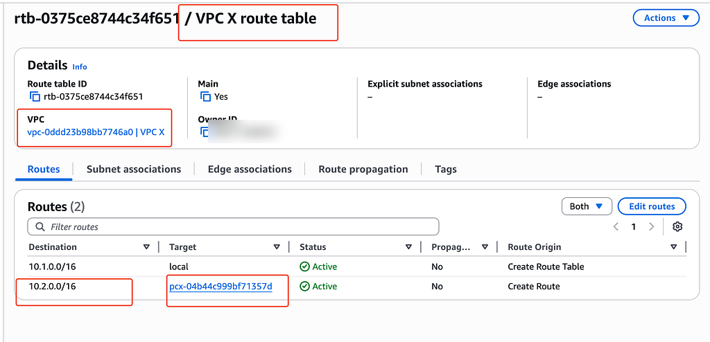
VPC X routes VPC Y traffic through the peering connection
In VPC Y I routed 10.1.0.0/16 back through it.
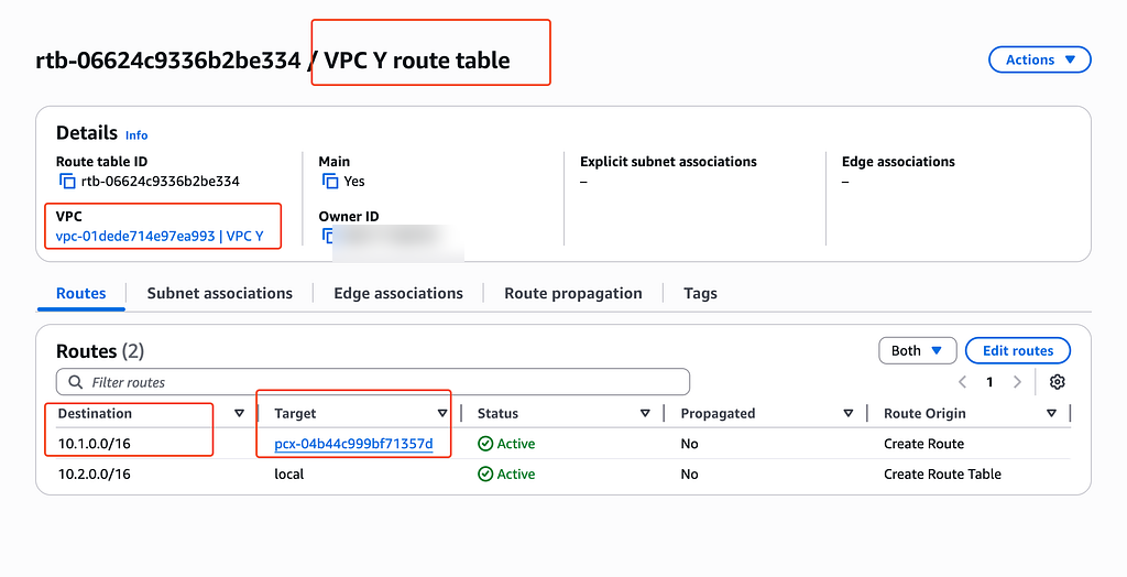
VPC Y contains the required reciprocal route
An active peering connection isn’t enough on its own. Both route tables need a return path.
5. Checking private connectivity
I tested between the instances with their private IPs. The replies showed the routes and security groups worked both ways.
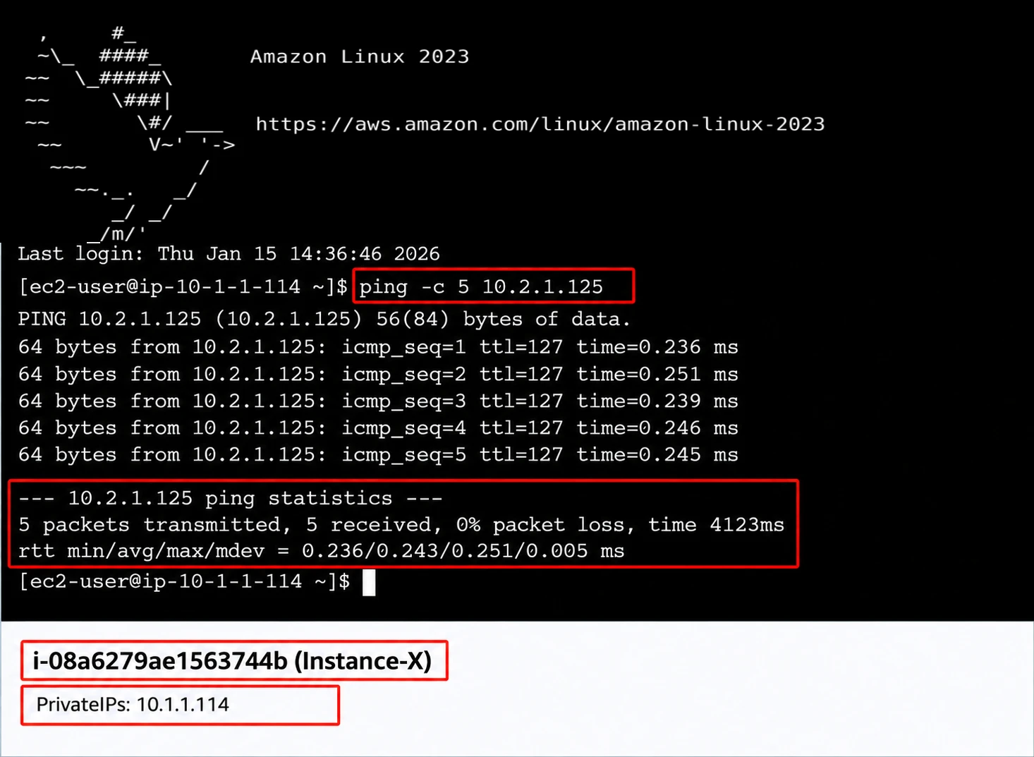
Successful private connectivity across the VPC peering connection
Part 3: Segmenting multiple VPCs with Transit Gateway
Goal
The last build used Transit Gateway as a hub for four VPCs. Dev, QA, and production all needed shared services. They were not allowed to talk to each other.
The policy I wanted:
- DEV can reach Shared Services.
- QA can reach Shared Services.
- PROD can reach Shared Services.
- Shared Services can return traffic to all three environments.
- DEV, QA, and PROD cannot route directly to one another.
1. Setting up four VPCs
I created these networks:
- DEV:
10.10.0.0/16 - QA:
10.20.0.0/16 - PROD:
10.30.0.0/16 - Shared Services:
10.40.0.0/16
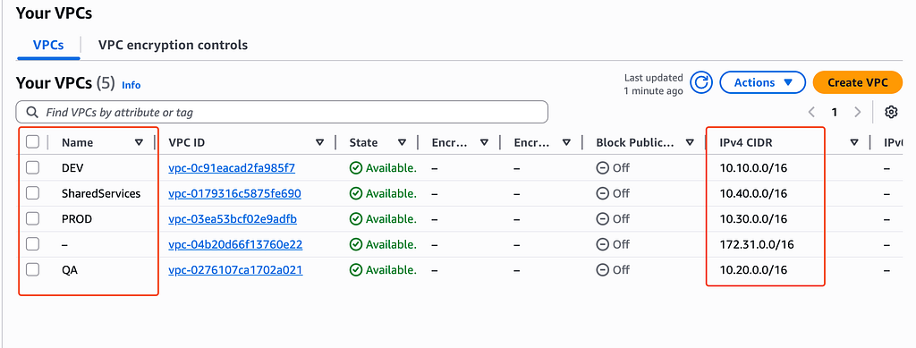
The four VPCs used in the Transit Gateway challenge
Each VPC had a subnet for the Transit Gateway attachment. None of the ranges overlap.
2. Creating the Transit Gateway
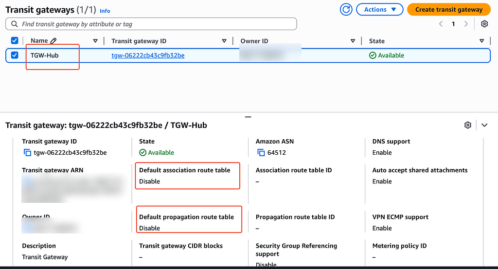
I created TGW-Hub and turned off default route table association and default propagation.
Transit Gateway with automatic association and propagation disabled
Turning off the defaults let me build the segmentation on purpose. This mattered. With automatic propagation on, everything could reach more than I wanted.
3. Attaching every VPC
I created an attachment for Shared Services, DEV, QA, and PROD. Then I waited for all four to come up.
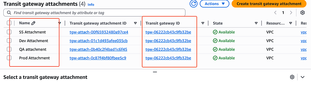
Four active VPC attachments on the Transit Gateway
Each attachment puts Transit Gateway network interfaces in the chosen subnets. The subnet route tables still need routes that send traffic to the TGW.
4. Separate TGW route tables
I made a route table for each of Shared Services, DEV, QA, and PROD. I didn’t want every attachment in one shared routing domain.
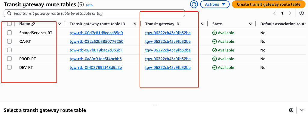
Separate Transit Gateway route tables for each environment
The DEV route table only learned the Shared Services prefix.
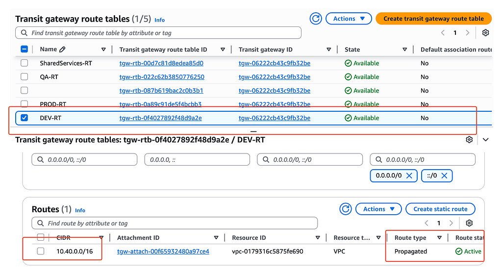
DEV’s Transit Gateway route table reaches Shared Services
The Shared Services route table learned the DEV, QA, and PROD prefixes. That lets return traffic reach every spoke.
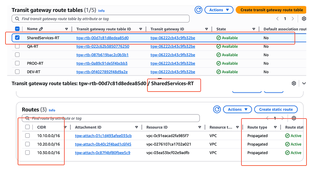
Shared Services has routes back to all three environment VPCs
I did the same for QA and PROD. Each one knew how to reach Shared Services. None had routes to the other environments.
5. Updating the VPC route tables
The DEV subnet route table sent Shared Services traffic to the Transit Gateway.
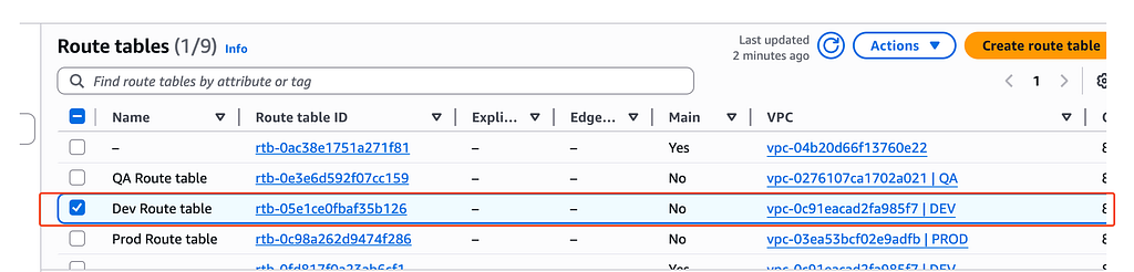
Selecting the DEV VPC route table
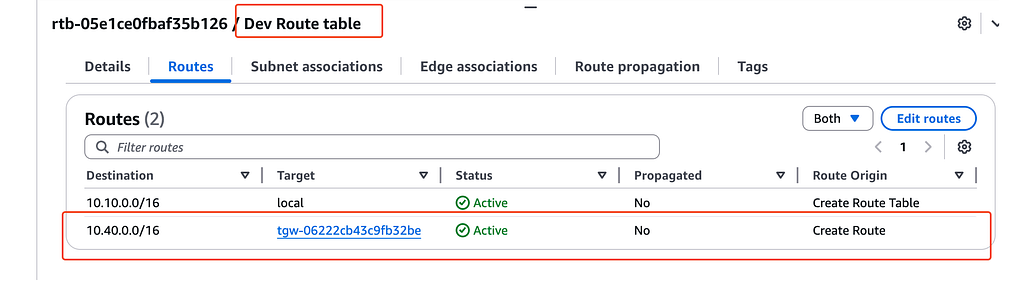
DEV VPC route table sends 10.40.0.0/16 to the Transit Gateway
The Shared Services route table had routes to DEV, QA, and PROD through the TGW.
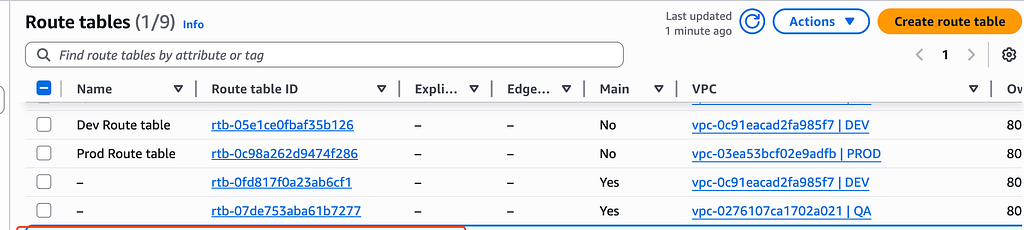
Selecting the Shared Services route table
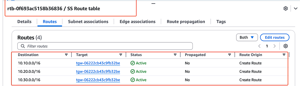
Shared Services routes the three environment prefixes to the TGW
This two-layer routing is easy to miss. The VPC route table gets traffic to the Transit Gateway. The Transit Gateway route table decides which attachment gets it.
6. Testing the segmentation
From a DEV instance, I confirmed it could reach the shared network.
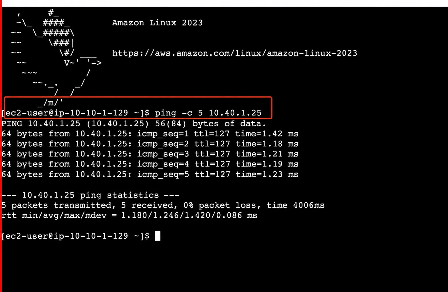
Connectivity test from DEV after the Transit Gateway routes were configured
Then I checked the full access matrix.
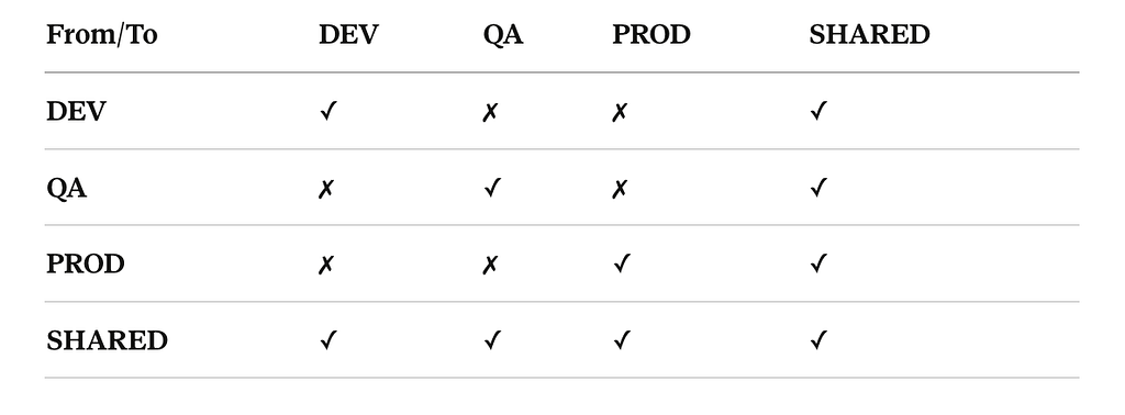
Final Transit Gateway connectivity policy for DEV, QA, PROD, and Shared Services
Checkmarks are allowed paths. X marks are blocked on purpose. I tested both sides. The paths that should work did, and the ones that should fail did.
How I troubleshoot VPC connectivity
When a test fails, I walk the path in this order:
- Confirm the source and destination IP addresses and DNS results.
- Check the source subnet route table.
- Verify that the internet gateway, NAT gateway, peering connection, or TGW attachment is available.
- Check the Transit Gateway association, propagation, and route selection when TGW is involved.
- Confirm that a return route exists.
- Check the destination security group and the source security group’s egress rules.
- Check stateless network ACLs in both directions, including ephemeral ports.
- Check the operating-system firewall and confirm that the application is listening.
- Use VPC Flow Logs, Reachability Analyzer, and application logs to find where traffic stops.
Result
I went from one VPC to a small multi-VPC network and kept the packet path clear the whole way. The first build covered public and private subnets, internet routing, NAT, and controlled admin access. The second showed that peering needs non-overlapping CIDRs and routes in both directions. The last one showed how Transit Gateway can centralize routing without letting every environment reach every other one.
The biggest lesson is that no single setting creates connectivity. A working path needs routes both ways, active attachments, security group rules, network ACLs, and the OS itself all lining up.